Disclaimer; the procedures in this article could expose you to electricity that could kill you if you do something stupid. If you’re not comfortable with that, hire an electrician to do this.
I recently purchased a CyberPower OL3000RTXL2U (aka OL3000) UPS for home use. The long fancy model number basically just means it’s an online UPS, 3000VA capacity, 2U size if you’re rack mounting it. By online, I mean a true double conversion UPS where incoming electricity is converted to the relevant DC battery voltage to charge the batteries, then an inverter on the other side of the batteries converts the outgoing DC current back to 120VAC. The benefits are elimination of EFI/RFI interference, no transfer time from line to battery since the power is always going through the battery, and it will happily run downstream from a generator while still spitting out pure sinewave power. That last point was my primary reason for the purchase; I have a noisy backup generator and whenever power goes out, the standby UPS’s just flip flop off and on until they ultimately self destruct. Online UPS’s happily take the poor quality generator power in and give you the good stuff on the other side for your devices.
Anyway, the CyberPower was purchased over a similar APC or TrippLite unit because of price; it’s cheap, under $1k. The secondary reason is that it has an L5-30 plug, which I needed. Lower VA-rating UPS’s generally don’t have those so they ruled themselves out. Here’s the unit on Amazon:
Now the whole point of writing this post; the NOISE. Jesus Christ this UPS is noisy. It sounds like my wife blow drying her hair if you’re in the same room with it. I didn’t want to relocate the UPS, but it was being put to use in an area within ear shot, and everyone found it quite annoying. I set out to see if I could quiet it down so I broke out the screw driver and went from there.
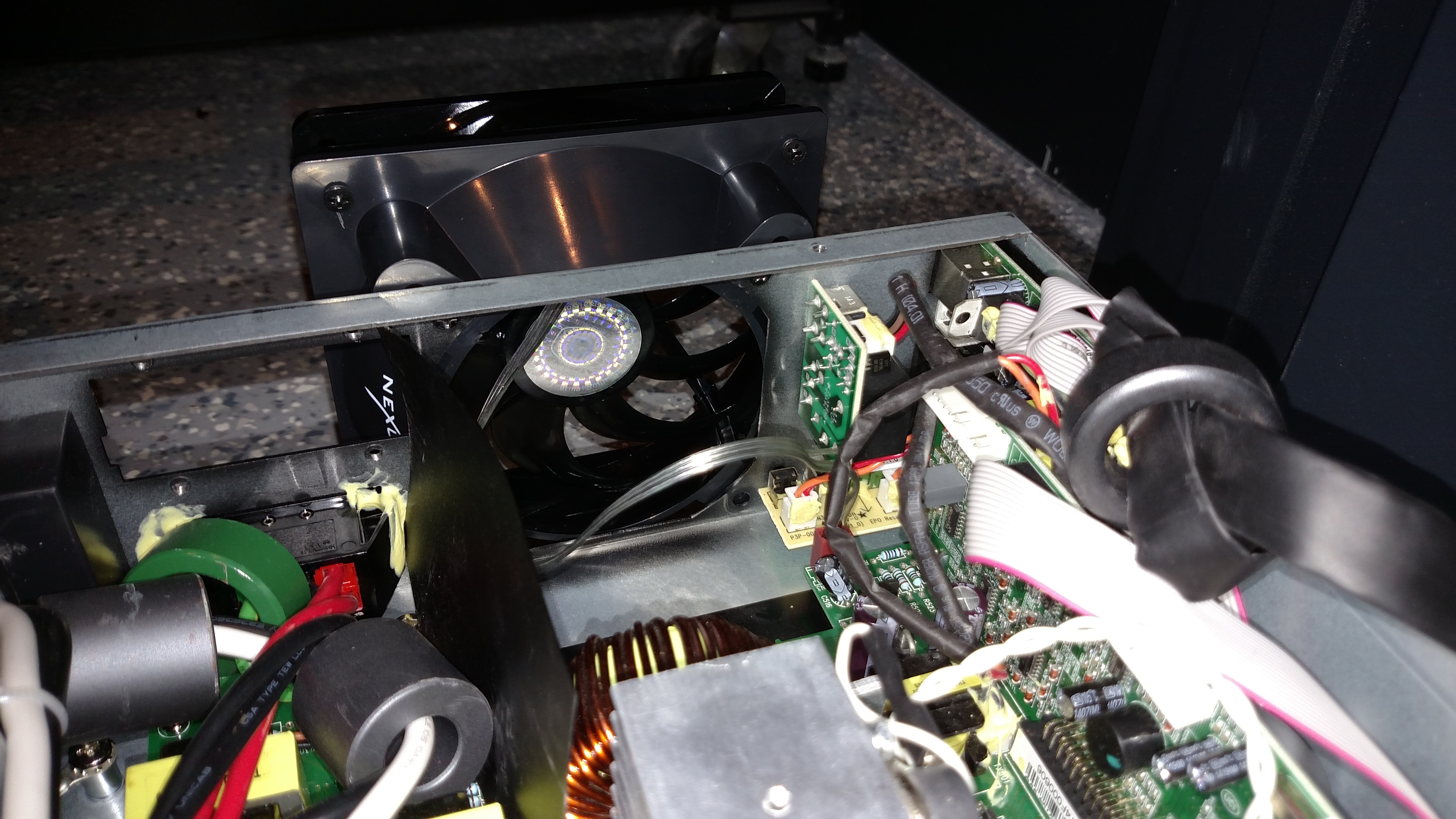
What you’ll find inside when you pop the top is an Aavid PSAD18025BH 80mm fan at the rear. This is a fast 5100rpm fan that moves just under 70CFM of air through the UPS when it’s in line mode. If power goes out and it is running entirely off battery, there is a second one of these fans at the front of the case that also cranks up so it doesn’t overheat. Since the second one is not normally operating, I didn’t spend any time on that one.
For the rear fan, I was going to try a few alternative 80mm fans scavenged from retired servers, but those were all equally high rpm models and just as noisy. I looked online at a bunch of fans meant for PC gamers and builders, but unfortunately all of the 80mm fans meant for that market run at a much lower rpm, to achieve quieter running, which in turn means a much lower CFM air movement. I figured going that route would be a very bad idea since the box would heat up a lot more.
What I ended up doing was adapting a 120mm fan to this system. If you run this unit in a vertical configuration, or a rack mount configuration where you have an extra U of space above and below it, then you can use my solution to achieve the same air movement and dramatically reduce the sound generated. Here’s the ingredients you need:
- Philips head screw drivers of varying size (small for case screws, larger for fan screws)
- Xacto knife or box cutter
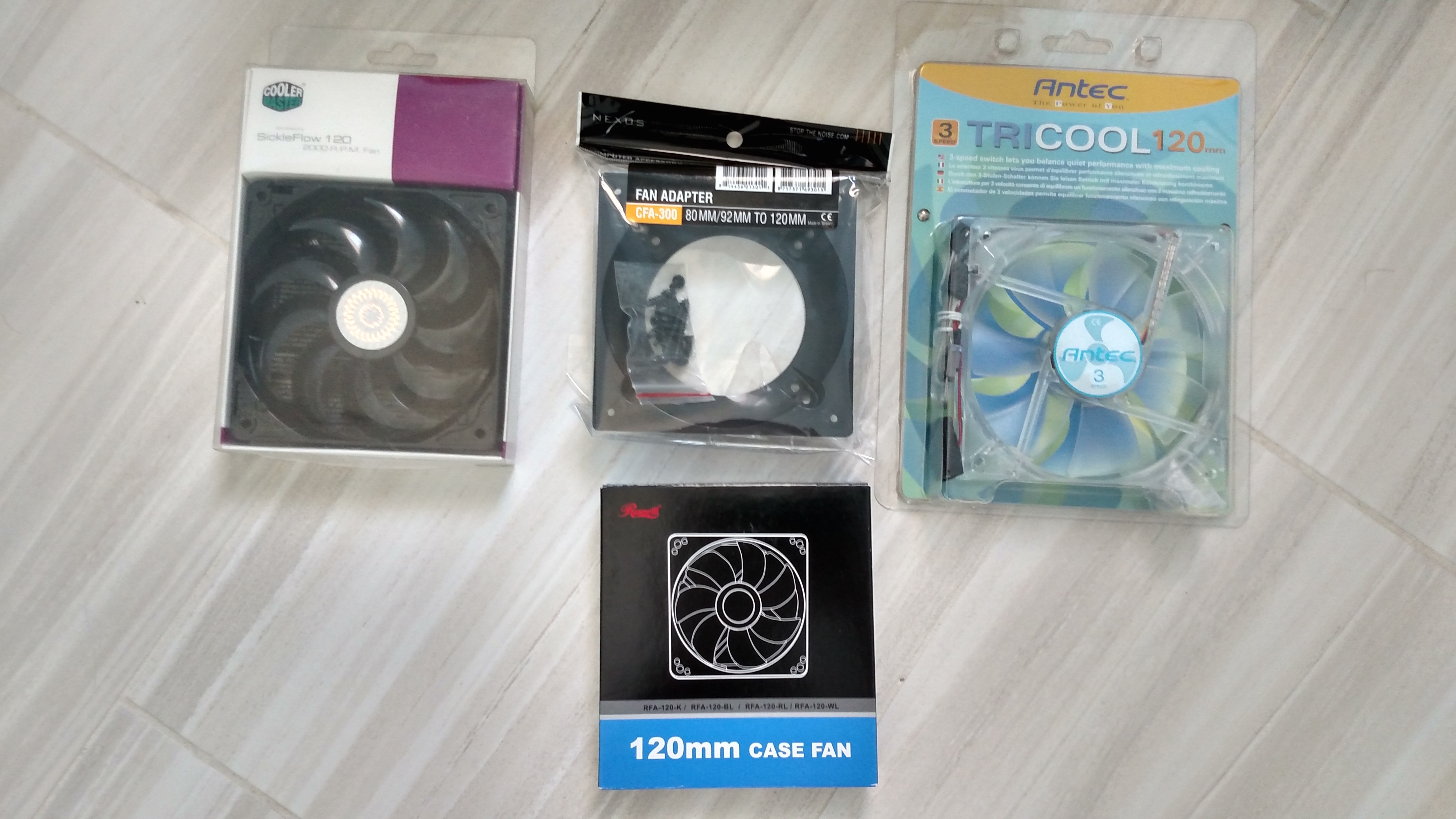
- Nexus 80mm to 120mm Fan Converter
- Cooler Master SickleFlow 120 – Sleeve Bearing 120mm Silent Fan
You’re certainly free to swap the fan out for one that you prefer, but I tried four and the Cooler Master was the quietest option that moved the same CFM as the stock fan, so that would be my recommendation. If you do use another, do NOT purchase a four pin fan meant for a gaming system where it has a PWM lead for the motherboard to control the speed of the fan; those will not work. You need a three pin fan where there’s just positive, ground and what is typically a yellow lead which is a tachometer. The UPS uses the tach lead to determine that the fan is still running. I fired it up with that lead disconnected and it would beep regularly about a fan failure. I’ve heard that it may be possible to short that lead to ground to not need it if you have a two pin fan, but don’t do that, there’s plenty of good three pin fans that solve the problem and you don’t want it failing without knowing. My fan tests included the following:
Here’s the steps on my ‘upgrade’:
- Unplug the unit and also disconnect the batteries (which unfortunately means undoing the front panel (two screws) and the plug (more screws)). Would have been nice if there were just a battery plug you could easily yank without needing a screw driver; APC does it like that.
- Pop the case open. There are three screws on the front top edge, three down each side, two top edge screws on the back.
- Disconnect the current fan from the case by removing its four exterior rear screws, but do not try to yank its power lead off yet.
- Disconnect the cover over the battery expansion block; this is to the lower right of the existing fan looking at the UPS from the back. The cover won’t be able to go back on and unfortunately this will also prevent you from adding a battery expansion later.
- Remove the cover plate for the SNMP card slot; it can go back on later.
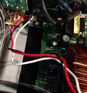
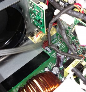
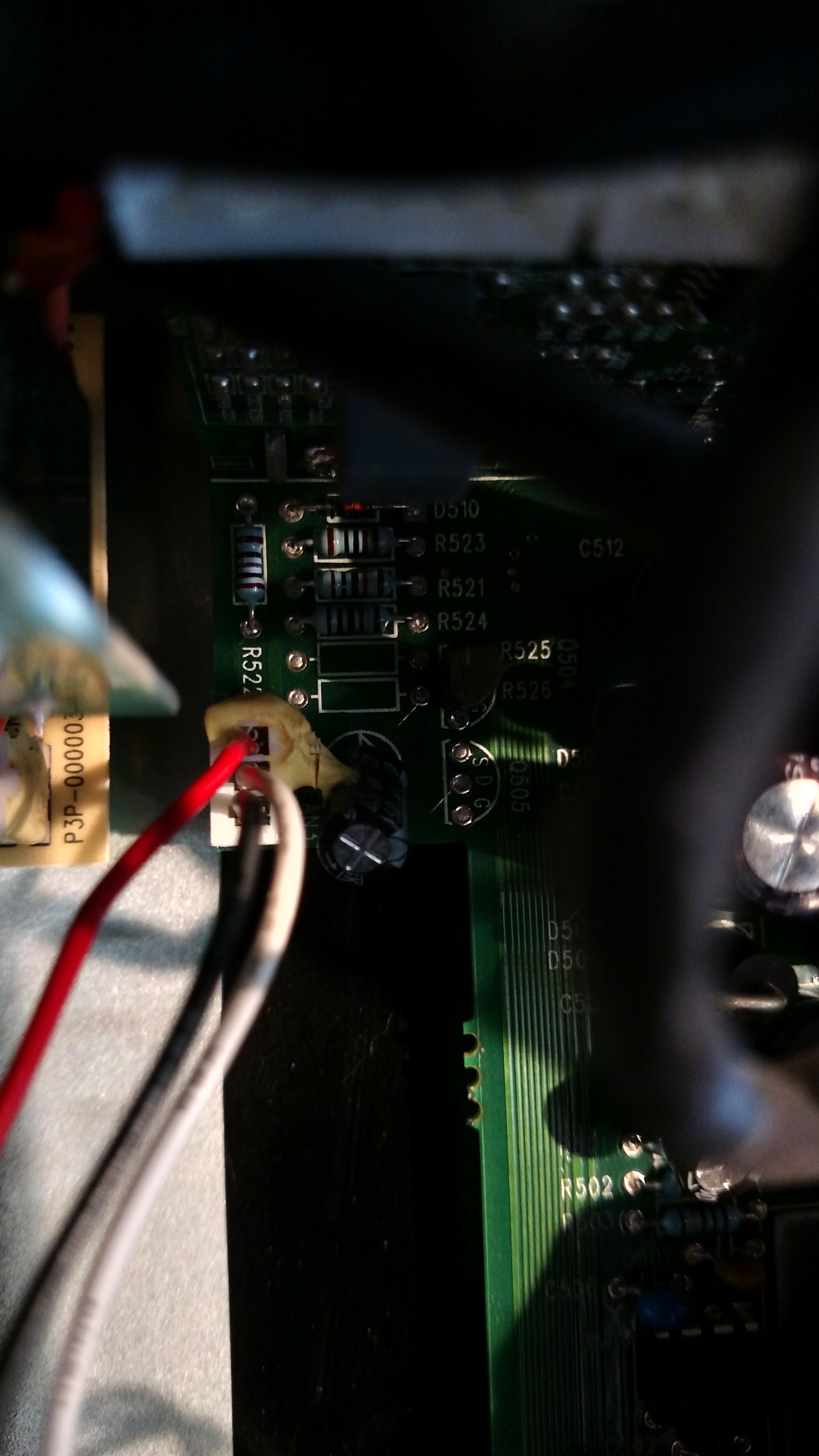
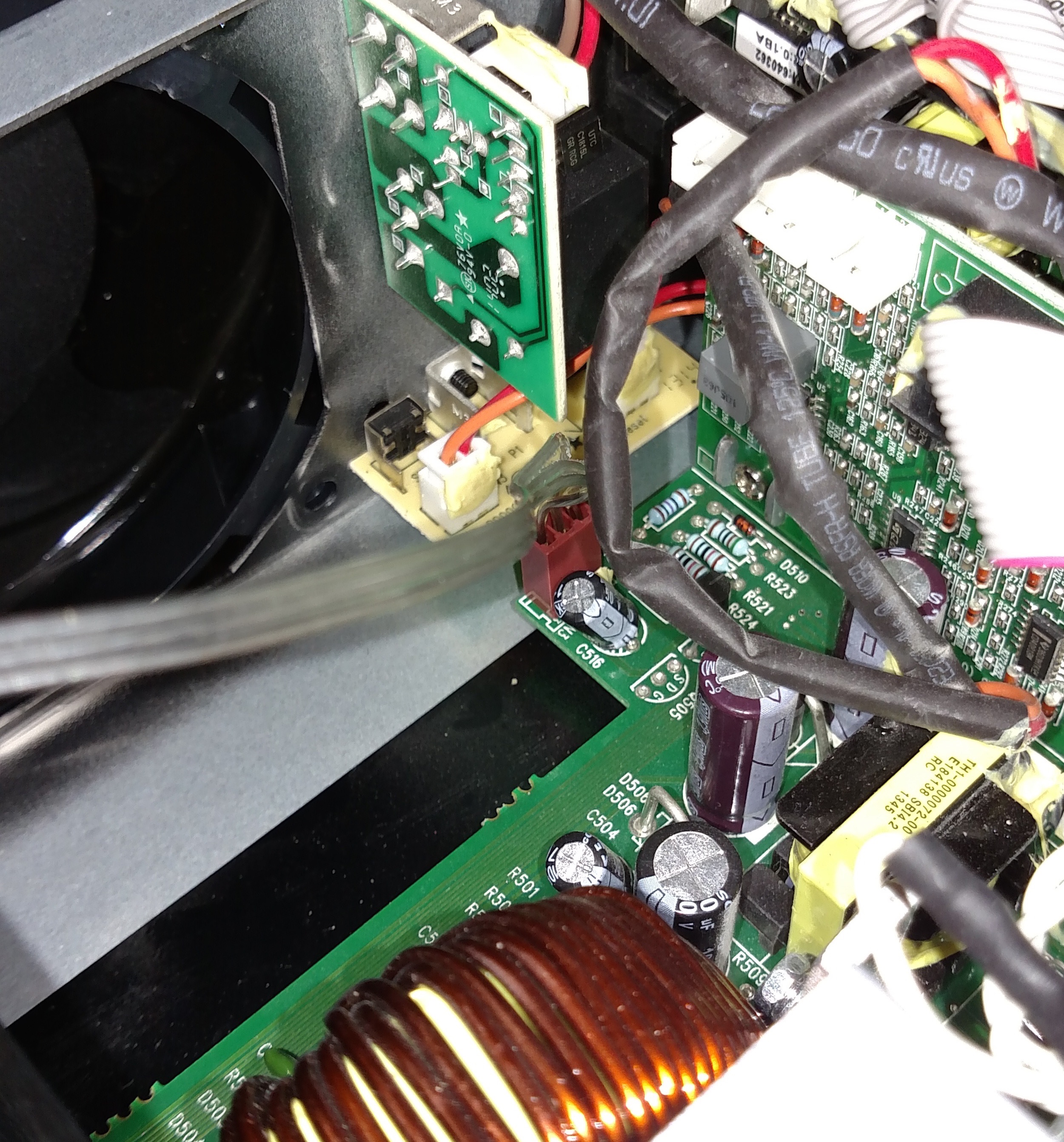
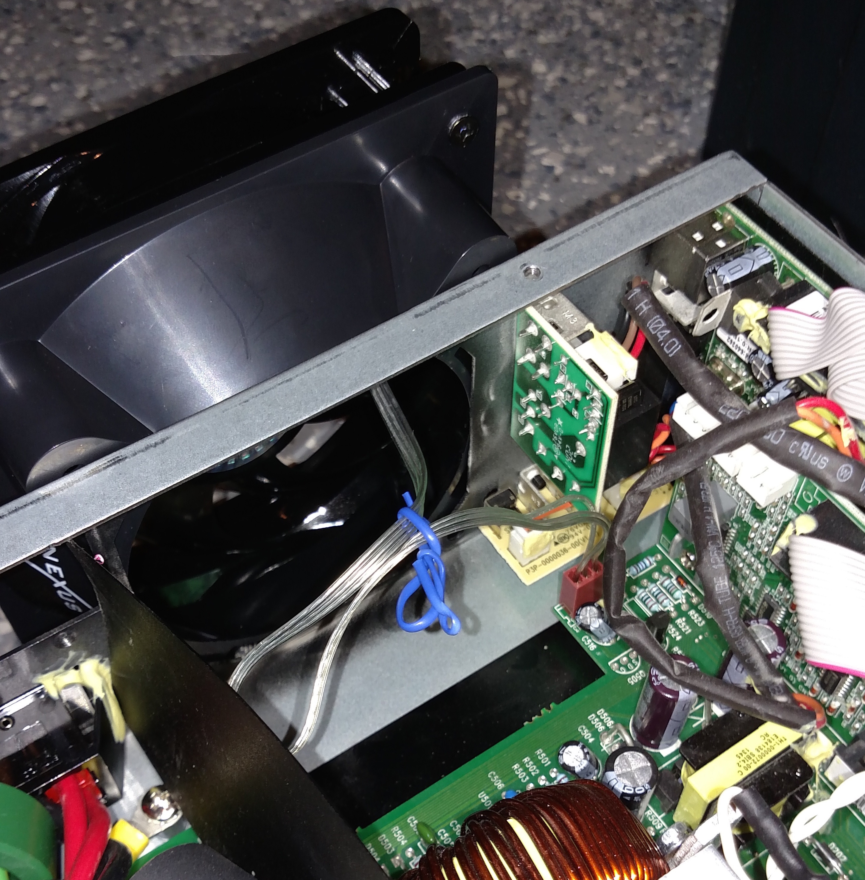
- Inside, you’ll find that the fan power lead is likely hot glued to both its socket and an adjacent capacitor on the system board, so if you try to pull it out, you’ll damage the capacitor in the process. This is where you need the Xacto knife or box cutter. I used a box cutter but the knife would be easier. I would recommend against a soldering iron or other hot object to try and melt your way through as it could damage the capacitor. With the box cutter, not applying very much pressure (since doing so moves the capacitor), I slowly ‘chipped’ away at the glue from the edge until I had removed enough that I could just press the razor through the remaining bit to free the plug from the capacitor. Then I removed any excess that was holding the plug into the socket until I could yank it out. I’ll include some pictures (click for full size).
Before cutting into the glue:
Starting the cut:

- Now that you’ve got the old fan removed from the case, you need to prepare the new fan. The connector on the system board is not the same as what your fans will come with. It’s an odd connector and an odd pin out. You need to remove the socket (aka pin header) from the system board; this is the plastic thing the old fan plug used to plug into. It will yank off, just give it a little force and it will slide off the pins. Try to avoid using pliers since you’ll be very close to components that could be damaged.
- Next step is preparing the fan power connector. The default for a 3-pin PC fan lead is to have the wires go tachometer, positive, negative if looking at the connector from the side with the exposed metal squares; opposite the side with the plastic ridges. You’re going to remove two of the three leads, but DO NOT remove all three or you’ll never know which ones are which because this fan uses a stupid cable that is not color coded, so if all three come out, you won’t know left to right. Anyway, you need to press reasonably hard with your razor blade into the metal squares to release the positive and tach leads out of the connector; this will be the left and middle slots, not the one on the right which stays in the connector. Don’t give it too much force, just enough to let you yank those two cables out of the connector. Once out, you may need to bend the cable leads back out a little if you flattened them while trying to remove them. Insert them back in opposite order where the positive (middle) is now on the left/outside of the connector opposite the negative, and the tach is in the middle. Make sure they’re in there securely.
- Use the self-threading screws that come with the fan to screw it into the 80mm to 120mm fan adapter. These are screws that look a little short and stubby and have reasonably course threads. MAKE SURE you pay attention to the fan direction marking on the housing of the fan. This fan needs to be installed in a pull configuration, so the arrow indicating air flow needs to point away from the adapter you’re screwing it to. Thread the power lead through the other side of the fan housing, and through the adapter out the 80mm side, then attach the fan to the adapter housing. When attaching it, do not over torque the screws, you don’t need to.
- Once attached, use the screws that came out of the original CyberPower fan to screw from the INSIDE of the UPS through into the adapter’s 80mm holes on the outside of the case. The top two are very easy. If you choose to attach the bottom two, you’ll need a very long screw driver because you won’t be able to get the correct angle to do it from in the case. I ended up leaving the bottom two out as it had a pretty good seal regardless.
- Plug the new fan connector into the three leads poking out of the system board. The negative should be the left-most lead looking at the UPS from the front; i.e. connect it where the ridges of the connector face the front of the UPS, not the back. Don’t use too much pressure, it will slide on easily.You won’t see the ridges in my connector image because I had sliced them off originally thinking it might fit in the stock socket, but it didn’t. The ridges would have been on the side that is visible in this picture.
- Tie the excess fan wire up so it can’t get sucked into the fan.

- Power it up and test it. The front fan may initially come on and make a bunch of noise but then it should calm down and be nice and quiet. If all is well, power back down, put it back together, put the cover back on the SNMP slot and throw it in the rack or vertical mounts.
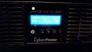
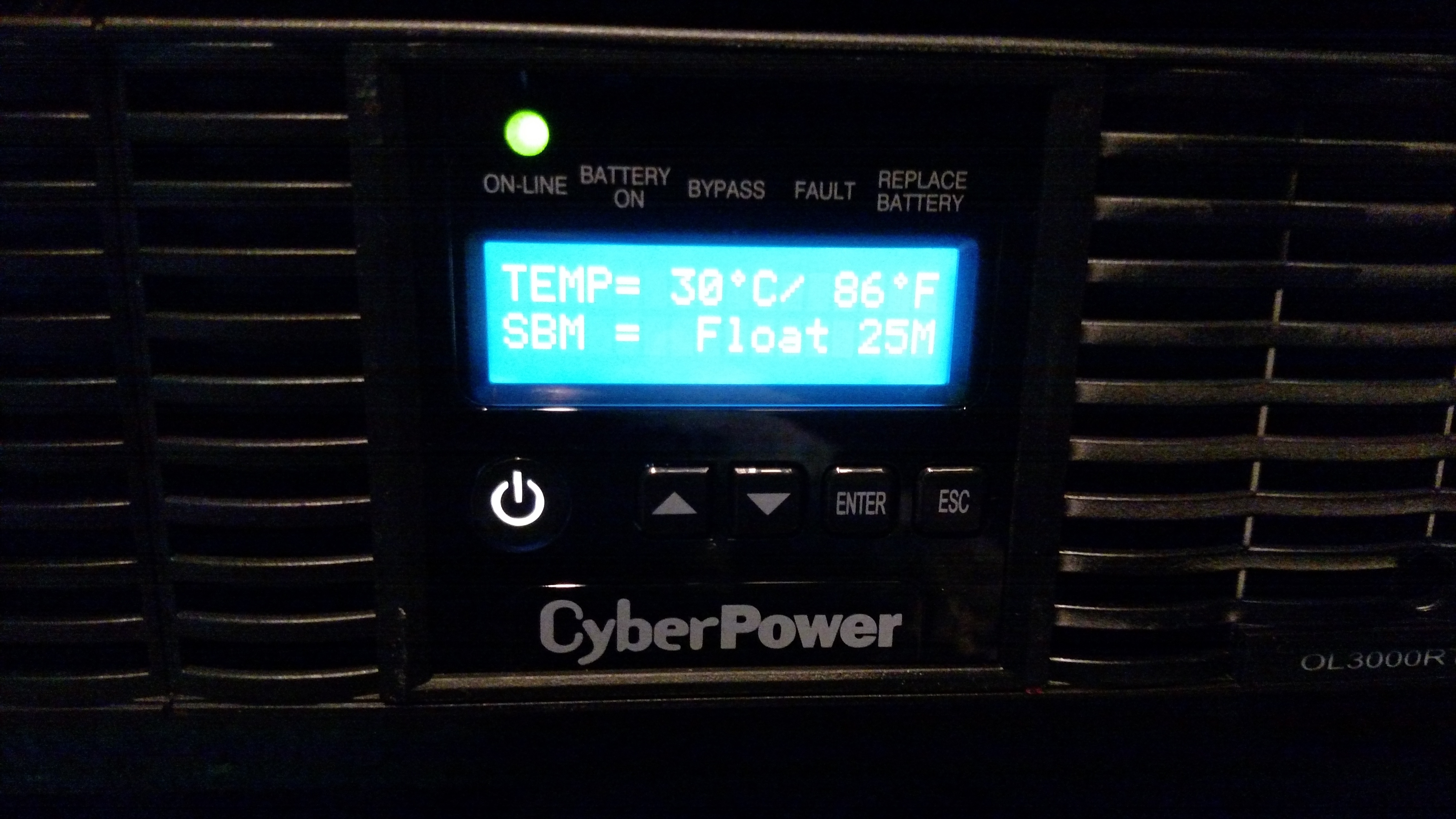
- Let it run for a bit and check the temp via the LCD panel.
- Now you have a MUCH quieter UPS with the same air throughput as you started with. If CyberPower is listening, I’d love a 3U version of this UPS with quiet fans.
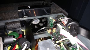
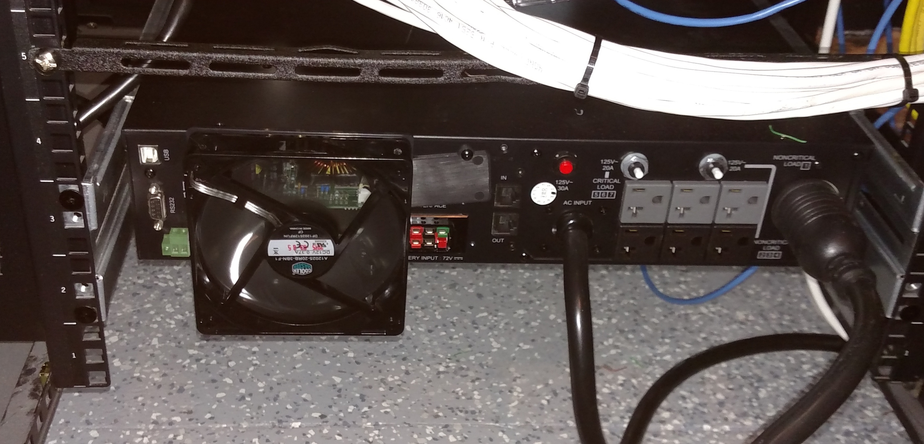
- Here’s how it looks in the rack afterward:


I appreciate your post and the photos and procedure is pretty great. I do not understand your steps # 4-8, especially since this breaks the expansion capability. After step 3, why don’t you just cut the existing fan wires and splice in the new one? You could even go with solder or wire crimp/nuts if you are worried the connection will open.
Even if the color coding doesn’t work, any continuity tester or the old/new fan should help you identify which wire is which fairly quickly. Also, even if colors are an issue, all the units should be consistently coded, so white, black, and red wires should always have the same function. You did the work, but did not list which wire is +/ground/tach. Also, + and ground should be reversible and the fan should still function.
Breaking the expansion capability was unavoidable with the 80-120mm fan adapter funnel I could find. There is not one that I could find that not cause that issue. For it to not cause the issue, the funnel would have to retain the original fan’s dimensions for several inches before growing out to the 120mm width.
Regarding your comment “did not list which wire is +/ground/tach”, to clarify, the system board is pinned out as negative, tach, positive. I did list in step 11 that, looking at it from the front, the left-most pin is negative, and from step 8, I gave the order of the pins.
Regarding your other comments; I think most people would agree that it is far easier to re-pin a simple connector than soldering light gauge cable, and cutting the cable would also prevent you from putting the UPS back to standard configuration if you ever need warranty service or sell it.
Thank you very much for the detailed solution! Our new UPS is driving us crazy!!!! (it is for a server). Our electrician just followed your steps, replaced the fan, but the new fan is not “moving”, despite the fact the the UPS identifies the fan as being ok… Any idea what the problem could be?
Only thing I can think of is the cables were not attached in the proper order or the fan is faulty. One lead is the ‘sense’ lead which tells the UPS the fan is operating, the other two are for power. If the sense lead is shorted to ground, it will simulate a working fan and the UPS won’t realize it is not running. If you’re looking at the UPS from the front, the pins are negative on the left, sense in the middle, positive on the right.
One comment on this conversion. Even though the SickleFlow 120 spec cfm are same as the stock PSAD18025BH, the static pressure are significantly different.The SickleFlow 120 has static pressure rating of 2.94 mmH2O while PSAD18025BH has 10.56 mmH2O. The difference is factor 3.59. Therefore, if I understand fluid dynamics correctly, the stock fan will move air much better in the environments that have lots of obstructions, and I speculated it is very cluttered inside that UPS.
Said that, I did read a review on Amazon for 1500VA version of this unit and person replaced the fan with much weaker 80mm fan. That seemed to work for them.
So in the end this conversion probably will be fine.
Very good point. Fortunately I’ve managed to push memories of statics, thermo and my other undergrad classes well out of my mind, so I didn’t take that issue into consideration. I haven’t had the unit run for an extended period on battery to see if the fan still performs adequately under higher heat output. I’m hoping it is okay as there is a second of the OEM 80mm fans in the front that operates in push mode only when the unit loses power input, and the components in need of cooling are actually surrounded by a tunnel (removed in the pics) that channels the air only over the spots it needs to.
If I understand fluid dynamics correctly (and I probably don’t), the reducer adaptor for the 120mm fan funnels the fan’s air from a 120mm aperture to a 80mm aperture. Since area changes as a function of the radius squared the pressure should go up by the square of the radius change (120/80)^2 = 1.5^2 = 2.25. So the replacement fan spec increased by the area change of the reducer adapter results in 2.94 mmH20 * 2.25 = 6.615 mmH20 which gets it over half-way to the 10.56 mmH20 spec of the PSAD18025BH. For what it is worth. And I could be wrong.
Liked your approach. Just got my unit. Wondering if it would be possible to put a much larger fan, on the SIDE panel. The top panel actually but side of the heat sink.
When the unit is sitting on its side in rack, I have plenty of space above it.
Would not want to alter function of expansion connectors.
Could remove the top panel and make one out of similar material, that I cut a hole in and mount a jumbo quiet fan to which would suck hot air out the top.
Yep you could probably come up with something to vent it via the top panel; you’d need to just remove the rear fan to effectively convert that to an inlet. The front fan could remain in place as it’s a push not pull. There’s an air channel down the middle so you’d just need to be specific about the location of your add-on fan, and tap into the baffles that channel the air.
This modification worked great on my OL1000RTXL2U. It was actually much easier than anticipated. Thanks for the post.
Hello, I think I did exactly as you do, but the thing is even the fan is spinning, after a while the fan alarm just starts. Any idea? I think I did the wiring as yours. The fan is a Be quiet! Sllent Wings 2, any thoughts?
thank you for such a great guide.
Only thing I can think of is perhaps your fan pin out is different in a way that allows it to power the fan but the ground is connected to the pulse line, so the fan runs, but the UPS thinks the fan is not moving because it’s one solid signal?
So, what do you suggest? another fan? or maybe try a different pin out?
thanks!
Well, magically everything is working as expected without doing nothing.
I bought two need fans to try if it was a matter of the Silent Wings 2. But before I gave it a try. It wasn’t spinning, but the weirdest is that the fan alarm wasn’t sounding. I tried the original fan and same behaviour, no spinning nor alarm. So I went to have lunch thinking that I broke the ups very confused.
Now I came back, I was about to connect the original one, close the UPS and figure out if I send it to tech support. But I connected the Silent Wings once again, and now is spinning and no alarm is sounding, even I have it connected for a while.
Don’t know what is or was wrong.
That’s great news; sorry I wasn’t able to help.
Well… you were more than helpful with this step by step guide. I couldn’t done without you, since I know below zero about electronic. So thank you man for losing time writing it and helping others.
MTFBWY
Thanks! This worked on a 2014 OL1000RTXL2U!
a) Because the OL1000RTXL2U only comes with one rear fan but the OL1000’s front fan plug and capacitors appear to be populated on the main board, I moved the rear fan to the front of the case and performed your modification.
b) When going from off-line to on-line mode at boot, the MCU will occasionally alarm “FAN FAULT R” while trying to spin the rear fan up to a higher RPM, but the fault will be dismissed (red light will turn off, message disappears) if I quickly press the “enter” button when the fault first occurs.
c) The OL1000RTXL2U’s USB port is partially obstructed by the adapter shroud; the USB cable should be plugged in before the shroud is attached.
d) I marked the fan cable’s wires with a red and black marker to match the colors of the old fan.
e) The lip of the case goes between the adapter and case body, so I left a 1mm gap between the adapter shroud and case.
f) I added a 120mm fan grill, and tall rubber feet for horizontal mounting.
g) The fan cable may also be routed along the outside of the shroud and through the gap between the case cutout and adapter.
h) For easier mounting of the bottom screws, one may run the screws in and out of the bottom adapter shroud’s holes to widen and tap the adapter plastic, so less torque is required when turning a long screwdriver at an angle inside the case to mount the bottom screws.
Thanks again for your great instructions!
Awesome, thanks for the tips for others, and glad it helped.
Have an older 2200 and this worked great. Got a new 2200 and it has a 4 pin layout. Going to try with some noctua industrial fans (200 mm, because I can) . Pinout might match. Fingers crossed. Will update soon.
Hi,
Found this when looking for info on silencing online ups with a noicy fan.
I have a eaton pw9130i700t-xl, tower verson (?), not the rack type.
The fan is spinning and whining all the time and its really anoying.
The specs says that its outputting around 40 db (the fan) and pushing 53 CFM at 4000 rpm. 53 CFM is the same as 90 m3/h. I found a Cooler master blade master 80mm fan for replacement, this outputs almost 41 CFM at 2000 rpm and 28 db.
It should help alot with the noice i guess. But it will not be silent.
Thought that i could run it on battery for a while and meassure the temp on the output air, then change the fan and do the same again while meassuring the output temp. I guess it will get hotter if the fan isnt moving enough air through it..
Scientific right? Lol.. Atleast i guess i will be able to check if the exhaust temp is changing.
I use the UPS to run my NAS from it, so it can turn off properly in case of a power loss.
I found
Hmm I may have to check into their UPS’ for home; 40db sounds nice, I have a TrippLite online 1500 on my desk that is obnoxiously loud.
I’m going to perform that surgery on CyberPower OL1000EXL model which uses the same fan model PSAD18025BH once I receive the UPS and the replacement parts.
https://www.cyberpowersystems.de/fileadmin/user_upload/bilder/produkte/USV/frontback/FRONTBACK-OL1000EXL.jpg
Although the static pressure is not the same I don’t plan to use more than the half of the power at once, so the discharge current will be no more than 50% which will result in significantly lower battery temperatures, so I think this should work.
What confuses me more is that both cases have different volume and shape (mine is tower) and there is significant difference in power capacity (1000W vs 3000W) and they *still* uses the same (single) fan model which leads me to think that they are not really optimize for noise.
What I can do more is to try the maximum load with original fan and check the temperature, then to swap with Cooler Master SickleFlow 120 and if that is still OK to try with some of mine Noctua silent fans.
Hi YourMum,
Thanks for the post. I did exactly as explained, the new fan is working but the UPS keeps on beeping fan failure and doesn’t start up. Any idea what I can do?
Hmm, the only thing that should make it think the fan is not there would be the tach lead not being connected, or not providing it what it expects. That would normally be the yellow lead, but I suppose it’s possible a fan’s tach lead may be broken or otherwise not functioning properly. What fan did you go with?
I’ve tried 4 different fans. And I did switch positions of the tach lead with the positive of all the fans. The fans I tried are; Startech 80mm, Coolermaster Standard 80mm, Arctic F8 PWM PST (but only using the positve, tach and grnd) and Arctic F12 120mm. It will not stop giving me an error and beeps continuously.
Hmm, if the original one still works and the alarm goes away, I really have no ideas. You could try hooking the tach line on the OEM fan to something like an oscilloscope but that’s a lot of work just to see what kind of signal it’s outputting to then compare to the other fans.
Yes the original one still works. I cannot make it work. can I check that with a multimeter?
You could test it; but a multimeter would probably read positive voltage even if it were pulses and not actual solid. Someone told me a long time ago you could short that pin to ground and the device would think the fan was working, but then you won’t know if the fan actually does fail.
Thanks. So you don’t have any other solution?
Had the same problem but after a week i figured it out.. my cyperpower ups basically rejects anything below 0.3A fans so i attached a low noise adapter from noctua to a bgears 80mm 3500rpm fan (basically the same as what was in it but with normal pins). It is much quieter now. Not sure if it will last since obviously it is moving less air but so far the output temps are ok.
As an update, newer versions of OP’s UPS have 3 fans with PWM. All fans run always but just different speeds depending on temp. I exchanged all the fans for noctua fans of whatever size. 120, 140, 140. No particular order or reason just what I had available. All replacement fans had PWM. For Noctua, they have the color code online which is nice. The little fans pinout of cyberpower (Y Sun) are not available, but are easy enough to figure out. I cut the little fans cables in half to not have to mess with the board. Then I took the extra cable extensions from noctua cut those in half matched and the colors for each fan making sure to use the side that would mate with the fan and tossing the other half. That left white and green as the odd ones out. Solder them all together blue to blue, black to black, yellow to yellow, and then white (cyber) to green (noctua). Slap on some adapters for upgraded large fans to small fan holes. Multiple adapters if 140 or 200. The 3rd fan is the problem, 60mm, annoyingly loud, no room to add another fan of larger or quieter type internally. So I just cut a hole in the side face and slapped a large fan above the 60mm fan location. No faults and temp stable at 78F when RT is 73. Best part is noise level dropped from 45/52 to 18 to 29 db at max speed. Very quiet. My Dyson air purifier/ heater is louder. The older cyber power UPS I have is just as quiet but temp is 89.6 same RT. That one has a 200mm noctua on the back and a 140 coolermaster on the front and sits right under my desk at 14 to 18 db. Only because the cooler master has a weird noise to it occasionally.
In my brand new OLS1000ERT2U are two fans integrated, called DA08025B12HF with 12V DC and 0.40A, made by Shenzen Huaxia Hegtai Electronic.
The cryptic model name means:
DC Axial fan, 80x80mm Frame dimension, 25mm Frame thickness, Two Ball bearing, 12VDC, High Speed, Function FG. Function FG means it has a RPM measurement using a frequency generator. Its operating voltage is 7V-13.8V, input current 0.28A, 3.36Watt, 3000RPM, air flow 35.09 CFM or 1 m^3/min, static pressure 0.11 inch H2O or 2.8 mm H2O and noise level of 31dB. The cable pinout is: Red (+), Black (-) and 3rd wire is PWM for RPM measurement.
Both are running continously.
I try to replace them with Noctua NF-A8 FLX and hope it works. For comparison
Noctua 2000 RPM, 50 m³/h, 1.96 mm H₂O, 0.84 W
Default 3000 RPM, 60 m³/h, 2.80 mm H₂O, 3.36 W
Follow up:
Sadly it didn’t work. The UPS noticed the ‘malfunctioning’ fan and stopped working. Because I opened the device already and thus voided the warranty, but because I wanted the thing to work silently, I kept on figuring out a solution. This solution is difficult, requires some technical skills and you don’t have any information about the fan status any longer. In short: Don’t do it, if you don’t have to.
On the manufacturer homepage of the fan (Shenzen Huaxia Hegtai Electronic) you can find some informations about the RPM signal. The fan is a two pole motor, so each revolution two pulses are sent in an open drain connection. I hooked it up to an oscilloscope and got a 142Hz square wave at 12V, resulting in 4260 RPM. Installed in the Cyberpower it’s powered by 8.76V, resulting in 113 Hz and 3400 RPM. The Noctua fan delivers 64 Hz at 12V, resulting in 1920 RPM.
The solution was to build a square wave generator with an open drain output at 137Hz, simulation a fan with 4110 RPM. I used the NE555 with a 47k resistor and 100nF capacitor, installed the two Noctua fans, cut the RPM signal and installed my square wave generator instead.
Now it works and is silent. I don’t know how it performs under heavy load, but I hope that the high RPM signal is enough to keep it working. The cooling should be sufficient, at least I hope it. It’s not a tight installation and can use it’s case for heat dissipation, too.
@the author of this site: if you want pictures, schematics, … tell me and I will gladly deliver a more detailed description.
I don’t think I’d have put as much effort in as you have :-) I’m happy to post up the info though if you’d like to prep it and think someone else would benefit.
Hello
I ’m using OLS1000C, I have the same problem when I change to A8 fan.
Is it convenient to provide pictures, schematics?
Thank you.
Yeah – so I have an OLS1000E that the stock fan has just died so the UPS only powers on with FAULT 58 – which is the fan problem and then powers off again…
I too tried a noctura 80mm fan and hooked up red / black / yellow – only to have the fan spin, but powers down again with FAULT 58.
It’s the same fan model as you – DA08025B12HF – so chances are, it needs the same input modification to the tach input.
Do you have any other monitoring to indicate if the fan actually fails? or just feed the UPS BS and keep an eye on the fan?
I just feed the UPS BS and keep an eye on the fan :) I never had a failing fan and if the fan fails, the UPS could overheat and hopefully report an error.
I installed the NE555 module and the tests worked fine.
Hi, I have same problem with the A8 fan.
I want to know the NE555 module.
Is it convenient to provide pictures, schematics?
Thanks
After spending some time studying this – I created a schematic for the 555 timer to be able to fool the UPS into thinking it has a stock, operational fan.
https://www.crc.id.au/cyberpower-ols1000e-fan-replacements/
It also includes a bit of info for my ghetto construction including photos.
White cable is not tacho signal. It is rotation detect /RD signal. Check the original fan’s datasheet. Did you try to stop the fan from spinning and see if alarm works?